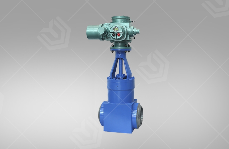
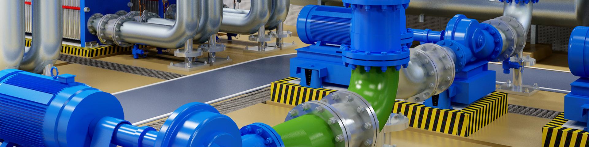


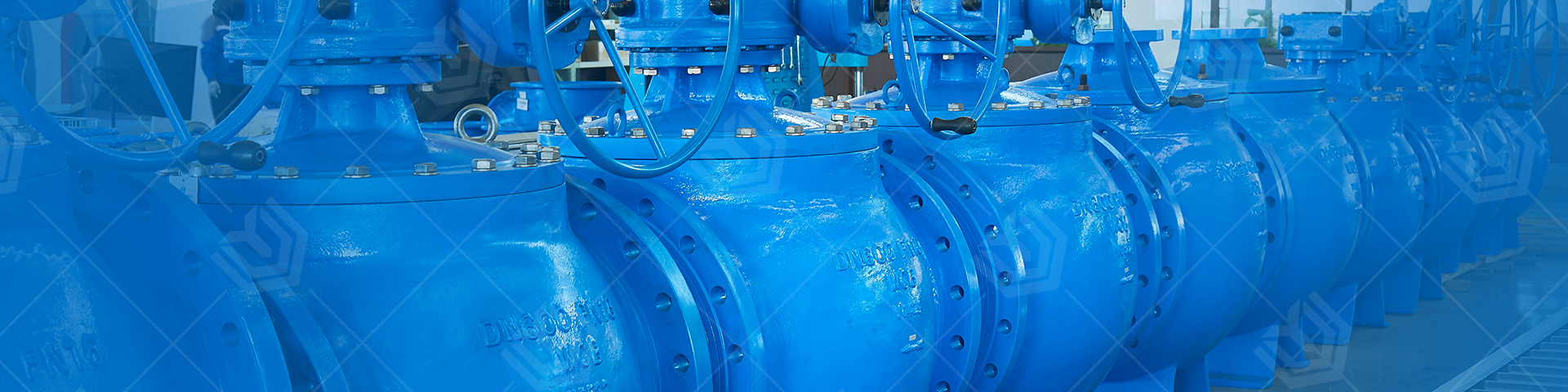
Product Description
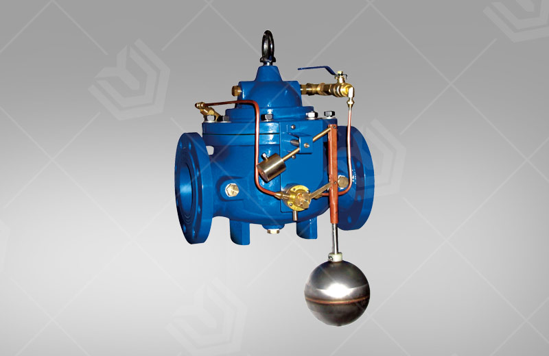
The 100D fixed water level valve is a diaphragm type valve that adjusts the liquid level of the water tank and the water tower. The valve is controlled by a floating ball. When the liquid level reaches the set height, the valve transmits the signal to the pump through the relevant structure, and the pump stops water supply; when the liquid level is lower than the set position, the pump automatically starts to supply water. The valve operates smoothly, effectively preventing the occurrence of water hammer when the pump is opened and when the pump is stopped, and avoids excessive pressure in the pipeline. It is suitable for automatic water supply system of water tank and water tower. The valve is easy to maintain, flexible and durable, and has high accuracy in liquid level control.
")
Main External Connection Dimensions
DN(mm) | 20 | 25 | 32 | 40 | 50 | 65 | 80 | 100 | 125 | 150 | 200 | 250 | 300 | 350 | 400 | 450 | 500 | 600 | 700 | 800 | |
L | 180 | 180 | 180 | 203 | 203 | 216 | 241 | 292 | 330 | 356 | 495 | 622 | 698 | 787 | 914 | 978 | 978 | 1295 | 1448 | 1956 | |
PN10 | D | 105 | 110 | 135 | 145 | 160 | 180 | 195 | 215 | 245 | 280 | 335 | 390 | 440 | 500 | 565 | 615 | 670 | 780 | 895 | 1010 |
D1 | 75 | 85 | 100 | 110 | 125 | 145 | 160 | 180 | 210 | 240 | 295 | 350 | 400 | 460 | 515 | 565 | 620 | 725 | 840 | 950 | |
PN16 | D | 105 | 110 | 135 | 145 | 160 | 180 | 195 | 215 | 245 | 280 | 335 | 405 | 460 | 520 | 580 | 640 | 705 | 840 | 910 | 1020 |
D1 | 75 | 85 | 100 | 110 | 125 | 145 | 160 | 180 | 210 | 240 | 295 | 355 | 410 | 470 | 525 | 585 | 650 | 770 | 840 | 950 | |
PN25 | D | 105 | 110 | 135 | 145 | 160 | 180 | 195 | 230 | 270 | 300 | 360 | 425 | 485 | 550 | 610 | 660 | 730 | 840 | 955 | 1070 |
D1 | 75 | 85 | 100 | 110 | 125 | 145 | 160 | 190 | 220 | 250 | 310 | 370 | 430 | 490 | 550 | 600 | 660 | 770 | 875 | 990 | |
H | 212 | 212 | 212 | 265 | 265 | 310 | 250 | 460 | 520 | 570 | 695 | 780 | 905 | 1025 | 1080 | 1030 | 1135 | 1270 | 1460 | 1640 | |
H1 | 179 | 179 | 179 | 210 | 210 | 215 | 245 | 305 | 365 | 415 | 510 | 560 | 658 | 696 | 735 | 610 | 665 | 725 | 865 | 975 | |
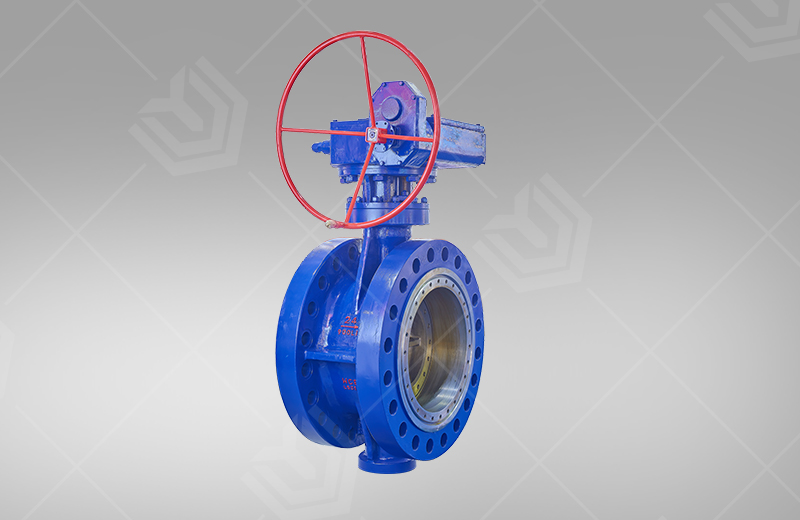
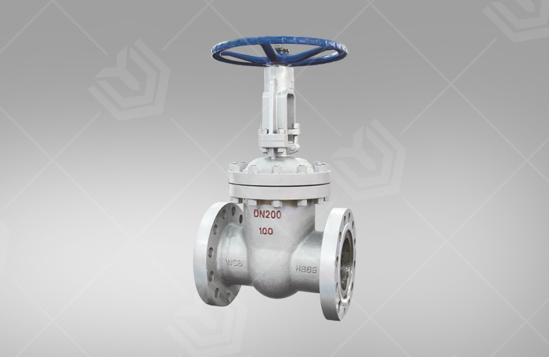
Note: In the installation diagram, the elastic seat gate valve or butterfly valve is optional, and it is recommended to choose a butterfly valve ≥ DN350.